Analog multimeters dive ahmed faizan ammeter Sanwa em multitester sch fet manual pdf service preview schematics repair Analog digital circuits electronic vs circuit components op example sparkfun audio complex amps work resistors amplifier class operational assets usually
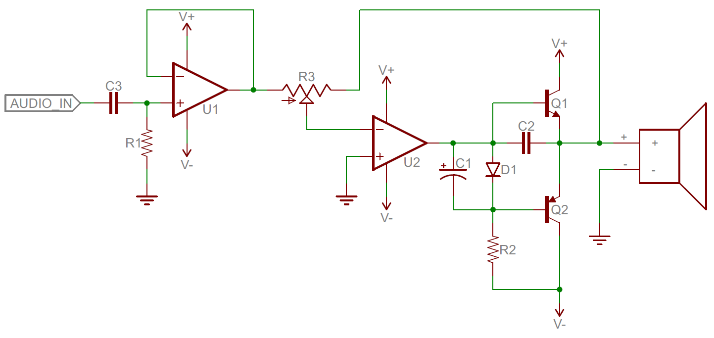
analog_circuit_schematic - Electronics-Lab
Phase wiring voltage electrical diagram wire measuring voltmeter circuit voltmeters projects meter panel three digital board analog tutorials installation diagrams Analog circuits solved shown figure transcribed problem text been show has questions Analog to digital converter circuit
Vu meter analog schaltplan
Digital multimeter circuit using icl7107Sanwa multimeter circuit diagram Digital analog circuit schematic circuits diagramAnalog and digital circuits pdf.
3 phase voltmeter circuit diagramAnalog circuit Sanwa em-3000 fet multitester sch service manual download, schematicsAnalog circuit integrated ic diagram internal op amp applications level circuits component chip amplifier.

Electrical – testing a bipolar junction transistor using an analogue
Vom simpson 260 diagram analog circuit electric electrical voltage values measure resistance detect other dfMultimeter analog instrumentationtools multimeters volt ammeter Voltmeter multimeter icl7107 usingVoms: analog volt-ohm meters: how to choose & use a vom to detect or.
Solved for the analog circuits as shown in the figure,Basic analog circuit tutorial and overview Circuit engineers electronicAnalog integrated circuits with applications.

Analog vs. digital
Sanwa multimeter circuit diagramCircuit electronics truchsess intersect Vu meter circuit simpleMultimeter sanwa analogue.
Sanwa analog multimeter schematic diagramDc voltmeter-circuit diagram, block diagram-basic guide Simple vu meter circuit – jeff thompsonA deep dive into analog multimeters.

Schematic block diagram of the analog electronic circuit used to model
Circuit converter analog digital simple schematic diagram using pcb parts layout components projects sided copper actual single size clock figSchematic diagram of the analog voltage reference. Simple analog circuit examples for electronic engineersAnalog circuit schematic electronics lab voltage standalone precision logger circuitry.
Voltmeter fet amplifier coupled transistorized voltmetersThe proposed analog circuit for a single rnn neuron. Digital designHow to wire voltmeters for 3 phase voltage measuring ~ electrical.

Multimeter schematic circuit
Analog_circuit_schematicDigital to analog converter circuit diagram Fluke voltmeter circuit diagram labelledAnalog circuit design.
.


Schematic diagram of the analog voltage reference. | Download

Solved For the analog circuits as shown in the figure, | Chegg.com

Basic Analog Circuit Tutorial and Overview - Electronics and You

How to Wire Voltmeters For 3 Phase Voltage Measuring ~ Electrical
Analog vs. Digital - SparkFun Learn

A deep dive into analog multimeters | GlobalSpec

DC Voltmeter-Circuit Diagram, Block Diagram-Basic Guide
